|
|
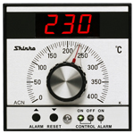
| Digital Temperature Indicating Controller |
|
| ACN-200 |
|
| Potentiometer analog setting
|
As easy to operate as our traditional model, the ACN-100 series.
Can set and change the SV easily using an analog setting unit (potentiometer). |
|
| The ACN-220 (PD control) comes with an Auto-reset function.
|
|
| Control action can be changed with the DIP switch.
|
|
Control action: PD or ON/OFF control is selectable with the DIP switch.
|
|
| Model |
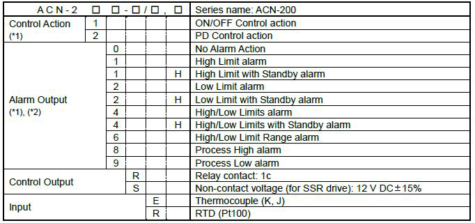
(*1) Control Action and Alarm Type can be selected with the DIP switch. When shipped, user specified
Control Action and Alarm Type have been set on the controller.
(*2) For the Alarm Action with Standby, “H” is attached to the end of the model name. |
| Rated range |
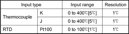
[ ]: One division of the setting scale
|
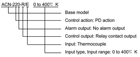
| Ordering example |
 |
 |
 |
| Rating |
| Rated scale |
Thermocouple
| Input |
Scale range |
Resolution |
| E |
K |
0 to 400 [5]* [5]* |
1 |
| J |
0 to 400 [5]* |
1 |
*: One division of the setting scale
RTD
| Input |
Scale range |
Resolution |
| R |
Pt100 |
0 to 100 [1]* |
1 |
*: One division of the setting scale
|
| Input |
Thermocouple |
K, J |
|
External resistance 100 or less or less |
| RTD |
Pt100, 3-wire system |
|
Allowable input lead wire
resistance: 10 or less per wire |
| Supply voltage |
100 to 240V
AC 50/60Hz |
| Allowable voltage fluctuation |
85 to 264V
AC |
|
|
| General structure |
| Dimensions |
96x96x120mm (WxHxD) |
| Mounting |
Flush |
| Material |
Case: Polycarbonate resin |
| Color |
Dark gray |
| Front panel |
|
| Indication
structure |
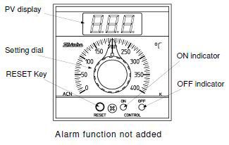
| PV display |
Indicates PV |
7-segment Red LED display 3-digit
Character size: 14.3x8.0mm(HxW) |
| Action indicators |
ON indicator
(Green) |
Lights when the control output is ON. |
OFF indicator
(Red) |
Lights when the control output is
OFF. |
|
|
|
| Setting structure |
| Potentiometer |
Sets the SV.
Scale length: 121mm (Angle: 240 degrees) |
| Function
key |
RESET
key: Performs Auto-reset. |
|
|
| Control structure |
| SV setting |
Analog setting with the potentiometer |
|
|
| Indication performance |
| Indication accuracy |
Within  0.5%
of each input span 1
digit 0.5%
of each input span 1
digit |
| Input sampling period |
250ms |
|
|
| Control performance |
|
| Standard functions |
| Attached functions |
Power failure countermeasure,
Self-diagnosis, Automatic cold junction temperature compensation,
Burnout Indication, Input abnormality, Warm-up indication |
|
|
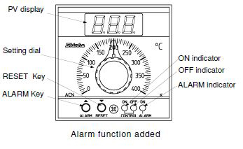
| Alarm Function |
| Alarm output |
The Alarm action point is set as a ±deviation from SV (except Process alarm). When the PV is out of the range, the alarm output turns ON or OFF (in the case of High/Low Limit Range alarm).
If the Alarm Function is specified, one type can be selected with the DIP switch: No Alarm Action, High Limit alarm, High Limit with Standby alarm, Low Limit alarm, Low Limit with Standby alarm, High/Low Limits alarm, High/Low Limits with Standby alarm, High/Low Limit Range alarm, Process High alarm and Process Low alarm.
| Setting accuracy |
Same as the Setting Accuracy of Control Performance |
| Action |
ON/OFF action |
| Hysteresis |
1 |
| Output |
Relay contact, 1c
Control capacity:3A 250 V AC (resistive load)
1 A 250 V AC (inductive load cos =0.4 ) Electrical life: 100,000 cycles ) Electrical life: 100,000 cycles |
|
|
|
| Insulation, Dielectric strength |
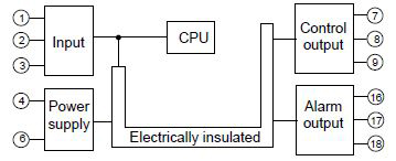
| Circuit configuration |
 |
| Insulation resistance |
10M or more, at 500V DC |
| Dielectric strength |
1.5kV AC for 1 minute (Between
input terminal and power terminal, Between control output
terminal and power terminal) |
|
|
| Other |
| Power consumption |
Approx.
5VA |
| Ambient temperature |
0 to 50 |
| Ambient humidity |
35 to 85%RH (Non-condensing) |
| Weight |
Approx. 370g |
| Accessories |
Mounting brackets: 1 set, Instruction manual: 1 copy |
|
|
|
|
| |
Alarm output: Setting by the deviation from the SV (except process alarm).
If the input goes outside the range,
the output turns ON or OFF (in the case of High/Low limit range alarm).
Alarm type: If any alarm type (except no alarm action) is specified, the alarm type can be changed with the DIP
switch. (Default: Customer specified alarm type)
| Alarm type |
Setting range |
SW2 |
SW3 |
SW4 |
SW5 |
| No alarm action |
─ |
OFF |
OFF |
OFF |
OFF |
| High limit alarm |
-199 to input span |
ON |
OFF |
OFF |
OFF |
| High limit alarm with standby |
-199 to input span |
ON |
OFF |
OFF |
ON |
| Low limit alarm |
-199 to input span |
OFF |
ON |
OFF |
OFF |
| Low limit alarm with standby |
-199 to input span |
OFF |
ON |
OFF |
ON |
| High/Low limits alarm |
0 to input span |
ON |
ON |
OFF |
OFF |
| High/Low limits with standby |
0 to input span |
ON |
ON |
OFF |
ON |
| High/Low limit range alarm |
0 to input span |
OFF |
OFF |
ON |
OFF |
| Process high alarm |
0 to input span |
ON |
OFF |
ON |
OFF |
| Process low alarm |
0 to input span |
OFF |
ON |
ON |
OFF |
|
|
|
| |
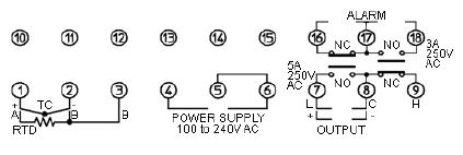
TC: Thermocouple input
RTD: RTD input
OUTPUT: Control output
ALARM: Alarm output |
|
|
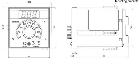
| |
External dimensions (Scale: mm) |
| |
|
| |
Panel cutout (Scale: mm) |
|
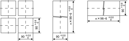 |
| |
Lengthwise close mounting
n: Number of units mounted |
Lateral close mounting
n: Number of units mounted |
|
|