|
|
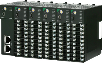
Modular Controllers
|
|
| QX1 series |
|
| Max. 1024 points measurement, control and monitoring |
| Max. 1024-point measurement and control |
Each control module offers controller functionality for up to four units and can be used individually or combined.
When used with a host, the modules offer flexibility in constructing both large-scale and small-scale systems.
Connected
Connecting the modules enables measurement and control of up to 1024 points.
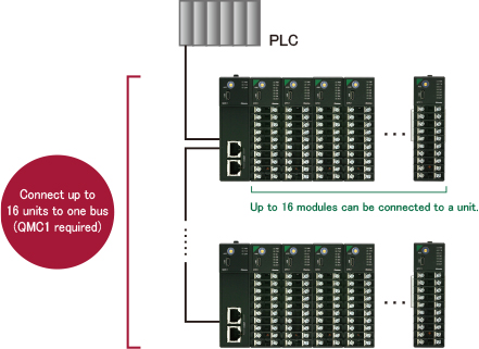
Stand-alone
When used independently, the modules can be used for control or communication with a host.
This make it easy to add monitoring targets.

|
Program-less connections to PLCs for reduced work
(SIF function) |
The Smart InterFace (SIF) function (program-less PLC communication function) enables direct connectivity to
PLCs from various manufacturers.


| Manufacturer |
Register |
Communication command |
| Made by Mitsubishi Electric (*) |
D register |
QR/QW |
| Made by Mitsubishi Electric |
R register |
QR/QW |
| Made by Mitsubishi Electric |
D register |
WR/WW |
| Made by Mitsubishi Electric |
R register |
WR/WW |
| Made by OMRON |
DM register |
FINS command |
| Made by Keyence |
DM register |
RDS/WRS |
|
| * |
The SIF function of the control module QTC1 is exclusively for Mitsubishi Electric Corporation
PLC D register QR/QW. |

| User layer |
TCP/IP
Mitsubishi Electric Corporation PLC MELSEC
Communication Protocol
Frame: QnA compatible 3E frame (SLMP 3E frame)
Code: Binary or ASCII
Connectable PLC: 1 unit |
|
Settings can be easily changed using the console software, making it possible to manage multiple
modules at once.
OS: Windows 10, Windows 11 (Japanese/English)

Please use Communication Expansion Module QMC1-C□ when replacing Shinko C series devices.
 |
 |
 |
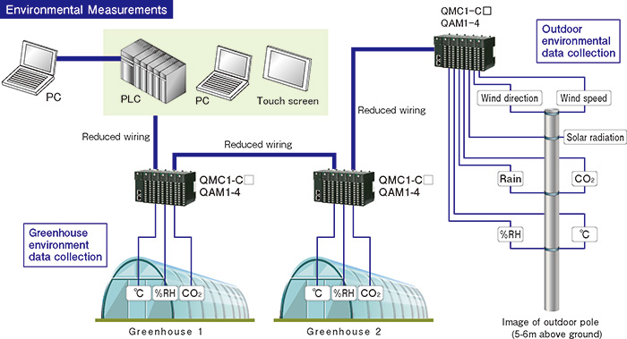
Usable as an analog module for reducing initial costs and wiring |
The QX1 series can be used as an analog module, helping to reduce initial costs and required wiring work.
|
Failure prediction maintenance |
Failure prediction maintenance
Check usage statuses using the following measurement functions.
1. Cumulative heater energization time (QTC1)
2. Cumulative module energization time (QMC1, QTC1)
3. Cumulative relay contact open/close count (QTC1)
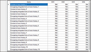
In the event of an error, the error number and energization time are saved.
The 10 most recent errors are saved. (Error history: Can be checked with console software) (QTC1)
The input difference detection function makes it possible to monitor for input differences between channels. (QTC1)
Risk avoidance in case of emergency
The output selection function can be used to switch between outputs. (QTC1)
For example, in the event of a CH1 output failure, CH2 output is enabled.
A signal can be output if heater burnout is detected. (QTC1)
[Heater burnout alarm options: Single-phase, 3-phase (3- phase: QTC1-2 only)]
Alarm output signals can be used to start or stop control. (QMC1-C□, QTC1)
[Event input/output (optional)]
|
 |
 |
Peak power suppression function for lower power equipment costs |
Peak power suppression function
The total current can be set for the module, and power suppression control can be performed when the sum
of the current values set for each channel is less than or equal to the total current.
This can help minimize investments in power equipment.
Example of peak power suppression function output timing

|
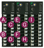
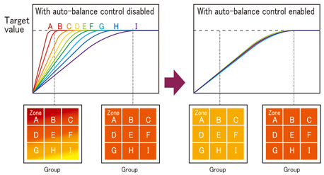
Multi-zone connection (Auto-balance control)
Take advantage of uniform control locations (zones) of a control target (group) through linking.
This helps prevent partial burning and mechanical distortion while also reducing adverse effects on product quality.
|
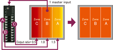
Individual output amount settings (output gain, bias control)
If required output amounts are known in advance, such as when controlling heaters in multiplelocations (zones) for
a single input point, uniform control of multiple zones is possible.
Combining output selection functions reduces the number of input terminals needed, initial costs can also be reduced.
 |
Five included control methods for reduced manual labor |
Control characteristics vary depending on the control target.
The QX1 series includes five control methods to meet a variety of control characteristics. |
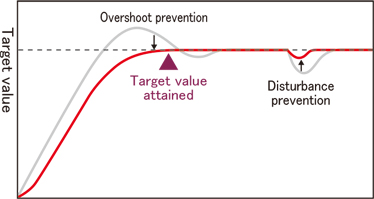
2DOF PID control
In addition to target value tracking and disturbance responsiveness, this well-balanced system reduces overshooting.
(When using default control action.)
Fast-PID control
This control method emphasizes target value tracking.
This control method works best when replacing the controller with a Shinko product.
(Doing so provides better performance.)
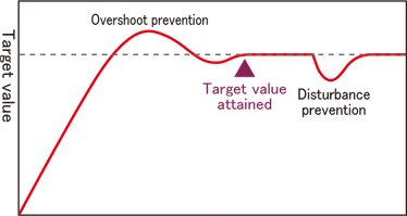
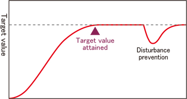
Slow-PID control
This control method prioritizes preventing overshooting rather than attaining a target value.
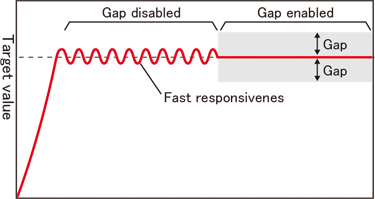
Gap-PID control
This control method is effective with fast responses such as for flow rates and valves.
(Deviation characteristics are provided within the gap.)
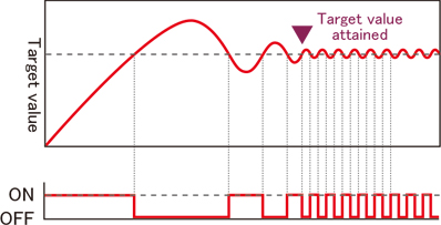
ON-OFF control
This control method is selected for operating devices that turn heaters and other equipment on or off.
|
 |
 |
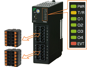
The numerous LEDs allow users to visually
check statuses and errors on-site.
The plug is removable, making wiring easy.
(connector type) |
 |
Setting can be easily changed using the
console software, making it possible to
manage multiple modules at once.
OS: Windows 10, Windows 11
(Japanese/English)
The plug-in construction of the modules
make replacement incredibly simple.
|
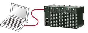
Commercially available cables (Micr USB Type-B) can be
used as connecting cables. |
 |
 |
 |
| Heating/cooling control |
Heating and cooling are controlled with CH1 used as the
heating-side input and CH2 as the cooling-side input. (Up to
2 loops are possible with the QTC1-4.) |
| Cascade control |
The adjusted CH1 variable, obtained from the SV and PV of CH1, is substituted for the SV of CH2, enabling CH2 control calculation and outputting.
(Up to 2 loops are possible with the QTC1-4.)
|
| Heater burnout alarm (optional) |
Detects and outputs heater burnout.
The CT and the connector harness WQ for heater burnout alarm
are sold separately. |
| Event input/output (optional) |
Event input (4 points) or event output (4 points) can be
added.
Connector harness EVQ for event input/output is sold separately. |
| Input difference detection |
Detects the input difference between two channels, and sets
a flag when the difference exceeds the set value. |
|
 |
| Model |
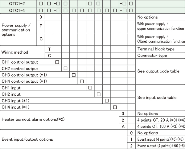
| (*1): |
For the QTC1-2, CH3 and CH4 are not available. |
| (*2) |
Cannot be added to Direct current output type or DC voltage output type. |
| (*3): |
CT and connector harness are sold separately. |
| (*4): |
Single-phase or 3-phase is available for the QTC1-2. |
| (*5): |
Connector harness is sold separately. |
| (*6): |
For the QTC1-2, Event input/output (2 points) |
|
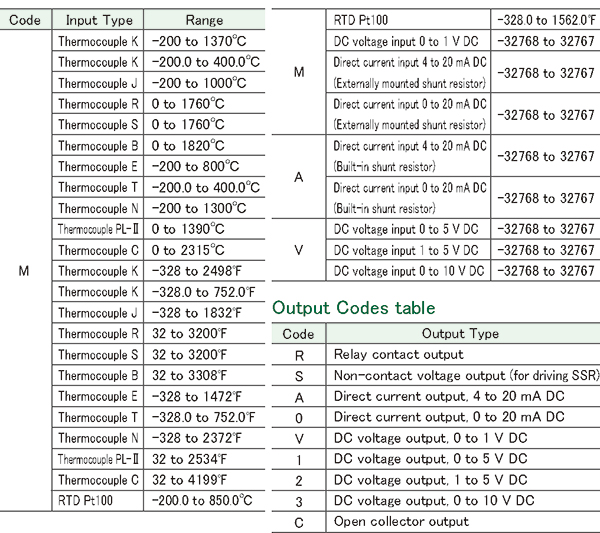
Input Codes/Output Codes
 |
 |
 |
Specifications
Summary |
Basic
accuracy |
At an ambient temperature of 23 and a mounting angle of
  5
degrees 5
degrees
| Thermocouple input |
Within  0.2%
of each input span 0.2%
of each input span
However, below 0 (32
(32 ):
Within ±0.4% of each input span ):
Within ±0.4% of each input span
R, S inputs, 0 to 200 (32 to 392
 ):
Within ):
Within  6 6 (12
(12 ) )
B input, 0 to 300 (32 to 572
 ):
Accuracy is not guaranteed. ):
Accuracy is not guaranteed. |
| RTD input |
Within  0.1%
of each input span 0.1%
of each input span |
| Current/voltage input |
Within  0.2%
of each input span 0.2%
of each input span |
|
Input sampling
period |
20 ms (current/voltage input only enabled)
50 ms (current/voltage input only enabled)
125 ms
Note: Fixed to 125 ms regardless of settings for thermocouple input and RTD input |
|
|
Communication
Specifications |
Power Supply /Host Communication function
| Communication line |
EIA RS-485 |
| Communication method |
Half-duplex communication |
| Synchronization method |
Start-stop synchronization |
| Communication speed |
9600, 19200, 38400, 57600 bps |
| Communication protocol |
MODBUS RTU |
|
Power supply / CUnet communication function
| Communication type |
Multi-drop |
| Communication method |
2-wire half-duplex |
| Synchronization method |
Bit-synchronous |
| Error detection |
CRC-16 |
Number of occupied
slave addresses |
1 |
Maximum number of
connected nodes |
64 nodes |
Communication speed
Communication distance |
Communication speed |
Maximum network length |
| 12 Mbps |
100 m |
| 6 Mbps |
200 m |
| 3 Mbps |
300 m |
| Isolation method |
Pulse transformer isolation |
| Impedance |
100 Ω |
| Termination resistance |
Last connection, set by CUnet slave This instrument is not equipped. |
|
|
 |
 |
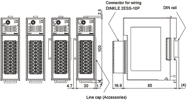
| Dimensions (Scale:mm)
|
QTC1-2, QTC1-4
Terminal block type
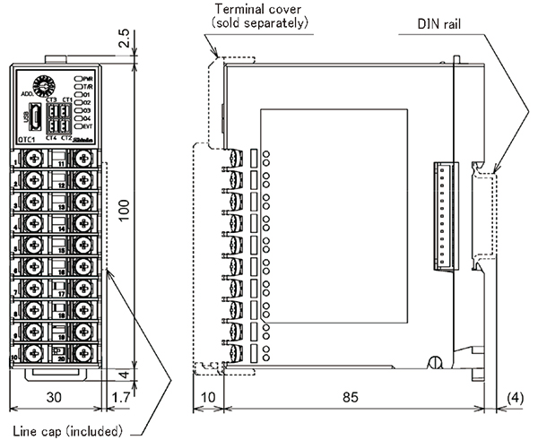
Connector type
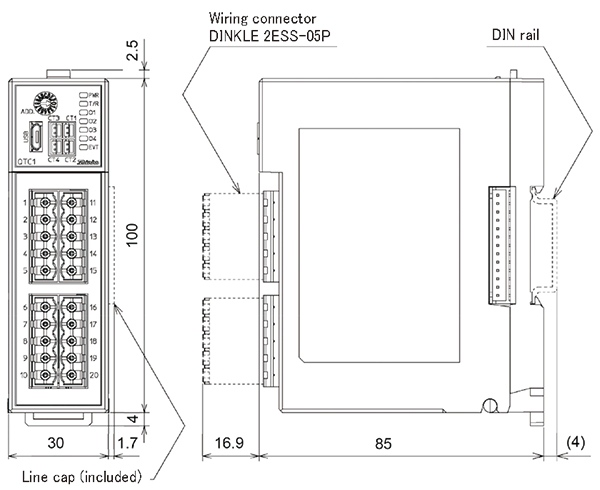
|
| Communication Expansion Module QMC1-C□ |
This instrument is a communication expansion module that connects to the control module (QTC1-□ ) for Ethernet communication.
A maximum of 16 control modules QTC1-20 (no power supply / communication option) (hereinafter referred to as QTC1-20) or QTC1-40 (no power supply / communication option) (hereinafter referred to as QTC1-40) can be connected via BUS, and a maximum of 64 points can be controlled.
| Model |

| (*1): |
When using the SIF function (Smart InterFace, program-less communication function),
to connect to a PLC manufactured by OMRON Corporation or KEYENCE Corporation,
cannot be connected with RS-485 communication type (QMC1-C5□).
Only RS-422A communication type (QMC1-C4□) can be connected. |
| (*2): |
The plug side connector of the event input/output connector is sold separately. |
|
| * The communication protocol can be changed using the Console software(SWC-QMC101M). |
| Communication Specifications |
Communication
lines |
EIA RS-422A compliant
EIA RS-485 compliant |
Communication
method |
Half-duplex communication |
Synchronization
method |
Start-stop synchronization |
Communication
speed |
Selecting 9600, 19200, 38400, or 57600 bps is possible using tha DIP switches. |
Communication
protocol
(Set with console
software) |
| Communication protocol |
Register |
Communication command |
| MODBUS |
- |
- |
| Made by Mitsubishi Electric |
D register |
QR/QW |
| Made by Mitsubishi Electric |
R register |
QR/QW |
| Made by Mitsubishi Electric |
D register |
WR/WW |
| Made by Mitsubishi Electric |
R register |
WR/WW |
| Made by OMRON |
DM register |
FINS command |
| Made by Keyence |
DM register |
RDS/WRS |
|
C series compatible protocols are selected by model name. |
Number of
connections |
Control module: Max 16 modules |
Power supply
voltage |
24 V DC Allowable fluctuation range: 20 to 28 V DC |
|
| Dimensions (Scale:mm) |
QMC1-C□
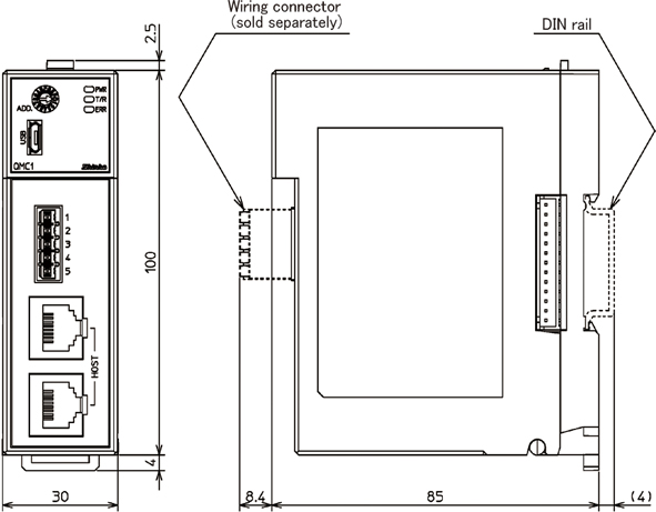
|
| Communication Expansion Module QMC1-MT |
This instrument is the communication expansion module for communication translation and data management.
Connects to control module (QTC1-□ ) for Ethernet communication (MODBUS/TCP or SIF function).
| Communication Specifications |
| Ethernet communication |
Connects to the control module (QTC1-□ ) for Ethernet communication (MODBUS/TCP or SIF function).
MODBUS/TCP
| Physical layer |
10BASE-T/100BASE-TX
automatic recognition |
| User layer |
MODBUS/TCP Number of connections: 1 |
|
|
SIF function
(Smart InterFace, programless communication function) |
This function reads and writes various data to PLC registers using the communication protocol of Mitsubishi Electric Corporation's PLC MELSEC.
| User layer |
TCP/IP
Mitsubishi Electric Corporation PLC MELSEC Communication Protocol
Frame: QnA compatible 3E frame (SLMP 3E frame)
Code: Binary or ASCII
Connectable PLC: 1 unit |
|
|
Module-to-module
communication |
| Communication line |
Internal Bus |
| Communication method |
Half-duplex communication |
| Synchronization method |
Start-stop synchronization |
| Communication speed |
57600 bps |
| Data bit/Parity/Stop bit |
Data bit: 8
Parity: Even
Stop bit: 1 |
|
|
| Power supply voltage |
24 V DC
Allowable fluctuation range: 20 to 28 V DC |
|
|
| Dimensions (Scale:mm) |
QMC1-MT
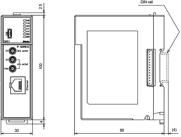
|
NEW
| 4 points Analog I/O Module QAM1-4 |
| Model |
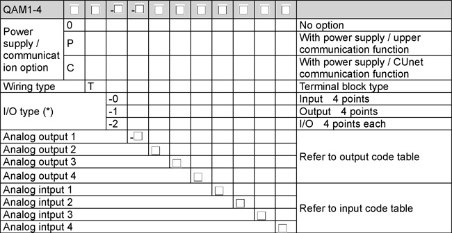
| (*): |
For input-only type, output code selection is invalid.
For output-only type, input code selection is invalid. |
|
Output Codes

| (*): |
Output code N is valid only when I/O type 0 (input 4 points) is selected. |
Input Codes

| (*): |
Input code N is valid only when I/O type 1 (output 4 points) is selected. |
|
 |
 |
Specifications
Summary |
|
Communication
Specifications |
RS-485
| Communication line |
EIA RS-485 (C5 option) |
| Communication method |
Half-duplex communication |
| Synchronization method |
Start-stop synchronization |
| Communication protocol |
MODBUS RTU or SIF specifications can be selected by DIP switch |
| Communication speed |
9600 bps, 19200 bps, 38400 bps or 57600 bps can be selected by DIP switch |
| Data bit/Parity/Stop bit |
Select the following with the DIP switch
Data bit: 8
Parity: Even, Odd, No parity
Stop bit: 1 or 2 |
Communication
response delay time |
Set the delay time to return the response from the module after receiving the command from the host.
0 to 1000 ms |
|
CUnet
| Connection type |
Multi-drop |
| Communication method |
2-wire half-duplex |
| Synchronization method |
Bit-synchronous |
| Error detection |
CRC-16 |
Number of occupied
slave addresses |
1 |
Maximum number of
connected nodes |
64 nodes |
Communication speed,
Communication distance |
Communication speed |
Maximum network length |
| 12 Mbps |
100 m |
| 6 Mbps |
200 m |
| 3 Mbps |
300 m |
| Isolation method |
Pulse transformer isolation |
| Impedance |
100  |
| Termination resistance |
Last connection, set by CUnet slave
This instrument is not equipped. |
|
|
 |
 |
| Dimensions (Scale:mm) |
QAM1-4
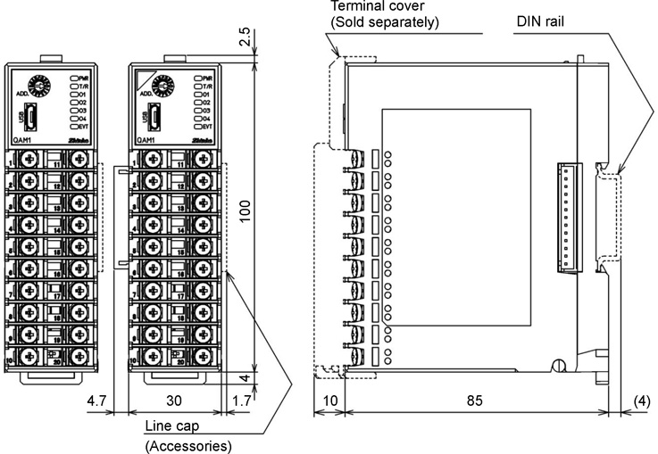
|
NEW
| Model |
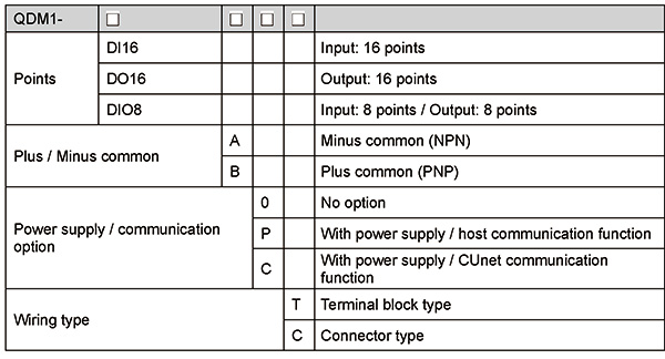
|
 |
 |
Specifications
Summary |
| Input rating |
| Common |
Plus/Minus common |
| Input points |
8 points/16 points |
Input status indicator |
Green (LED) lights up when ON |
| Allowable supply voltage for input |
24 V DC 10%, ripple content less than 5 %p-p |
| ON voltage/ON current |
15 V DC or more/3.5 mA or more |
| OFF voltage/OFF current |
5 V DC or less / 1 mA or less |
| Input current |
5.5 mA or less (at 24 V DC) |
| Input resistance |
Approx. 4.7 k |
| ON delay time |
0.2 ms or less |
| OFF delay time |
0.5 ms or less |
| Take-in cycle setting |
Setting range 1 to 100 ms at 1 ms, 5 ms by communication |
|
| Output rating |
| Common |
Minus common (NPN)/Plus common (PNP) |
| Output points |
8 points/16 points |
Output status |
indicator Green (LED) lights up when ON |
| Allowable supply voltage for output |
24 V DC 10%, ripple content less than 5 %p-p |
| Rated output current |
0.1 A/point, 1.6 A/common |
| Residual voltage |
1.2 V or less |
| Leakage current |
0.1 mA or less |
| ON delay time |
0.2 ms or less |
| OFF delay time |
0.5 ms or less |
| Overcurrent protection function |
Limit current value when overcurrent is detected |
| Output setting at communication error |
Output status (hold or OFF) can be set until normal data is received in the event of communication error (lasting 1 minute or longer) (factory default: hold) |
|
| Power supply voltage |
24 V DC |
| Allowable voltage fluctuation |
20 to 28 V DC |
| Power consumption |
Approx. 2 W or less |
| Ambient temperature |
-10 to 50 (no condensation or freezing) (no condensation or freezing) |
| Ambient humidity |
35 to 85%RH (no condensation) |
| Environmental specification |
RoHS directive compliant |
| Weight |
Approx. 160 g |
|
|
Communication
Specifications |
RS-485
| Communication line |
EIA RS-485 (C5 option) |
| Communication method |
Half-duplex communication |
| Synchronization method |
Start-stop synchronization |
| Communication protocol |
MODBUS RTU |
| Communication speed |
9600 bps, 19200 bps, 38400 bps or 57600 bps can be selected by DIP switch |
| Data bit/Parity/Stop bit |
Select the following with the DIP switch
Data bit: 8
Parity: Even, Odd or No parity
Stop bit: 1 or 2 |
Communication
response delay time |
Set the delay time to return the response from the module after receiving the command from the host.
0 to 1000 ms |
|
CUnet
| Connection type |
Multi-drop |
| Communication method |
2-wire half-duplex |
| Synchronization method |
Bit-synchronous |
| Error detection |
CRC-16 |
Number of occupied
slave addresses |
1 |
Maximum number of
connected nodes |
64 nodes |
Communication speed,
Communication distance |
Communication speed |
Maximum network length |
| 12 Mbps |
100 m |
| 6 Mbps |
200 m |
| 3 Mbps |
300 m |
| Isolation method |
Pulse transformer isolation |
| Impedance |
100  |
| Termination resistance |
Last connection, set by CUnet slave
This instrument is not equipped. |
|
|
 |
 |
| Dimensions (Scale:mm) |
QDM1
Terminal block type
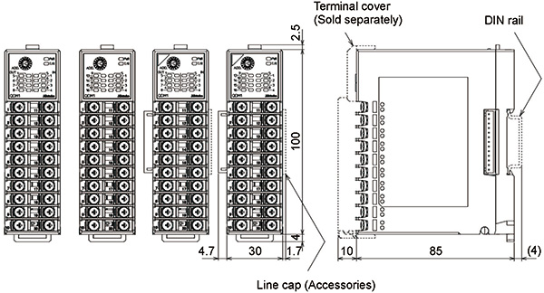
Connector type
|
|
