|
|
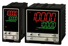
| Digital Indicating Controllers |
|
| ACD-13A, ACR-13A |
|
| ON/OFF SERVO Digital Indicating Controllers |
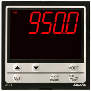
| Clear, large LCD display-Enhanced visibility !
|
Extra large LCD display
ACD-13A
ACD-15A |
PV display: 24.0 x 11.0mm (HxW)
SV/MV/TIME display: 14.0 x 7.0mm (HxW) |
ACR-13A
ACR-15A |
PV display: 14.0 x 5.4mm (HxW)
SV/MV/TIME display: 10.0 x 4.6mm (HxW) |
|
Comparison with Shinko controller JCD-33A
ACD-13A, ACD-15A
Shinko controller JCD-33A
|
| PV viewable even during control OFF ! |
4 choices during control output OFF function
PV can be indicated even during control output OFF, and an alarm output can be selected as well. |
OFF indication
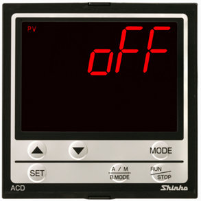
PV indication
 |
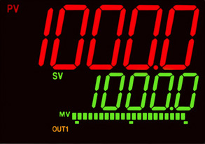
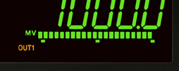
| Output MV can be viewed as bar graph
|
22-segment (-5 to 105%) bar graph
DV indication is selectable. |
ACD-13A
 |
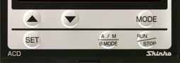
Basic settings and key operations are now doable via 3 key usage
(Increase, Decrease, Mode key) |
 |
| A variety of Input/Output Event functions ! |
Event input 4 points (option), Event output Max 5 points
Multiple Input/Output Event functions can be selected from; Alarm output,
Heater burnout alarm output (option), Loop break alarm output, Timer output,
Time signal output, Pattern end output, etc. |
|
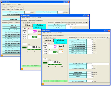
| Power via USB cable usable for setup
|
| If CMB-001 USB communication cable (sold separately) is used, a power supply for the controller is not necessary for initial settings.
|
Console software (SWS-AC001M) displays
 |
| Feedback potentiometer "Yes/No" selectable |
| Selectable using the front keypad. (ACD-15A, ACR-15A only)
|
|
| IP66 structure (for the front panel) allows usage in harsh environments where the controller is exposed to water or dust. |
|
 |
 |
| Rating |
| Rated
scale |
|
| Input |
| Thermocouple |
K, J, R, S, B, E, T, N, PL-II, C(W/Re5-26)
External resistance: 100 |
| RTD |
Pt100, JPt100 3-wire system
Allowable input lead wire resistance: 10 or less per wire |
| DC current |
0-20mA DC, 4-20mA DC
Input impedance: 50,
Allowable input current: 50mA or less |
| DC voltage |
0-10mV DC, -10-10mV DC, 0-50mV DC,
0-100mV DC, 0-1V DC
Input impedance: 1M or more, Allowable input voltage: 5V DC or less
Allowable signal source resistance: 2k or less |
0-5V DC, 1-5V DC, 0-10V DC
Input impedance: 100k or more, Allowable input voltage: 15V DC or less
Allowable signal source resistance: 100 or less |
|
| Supply voltage |
100to240V AC 50/60Hz, 24V
AC/DC 50/60Hz |
| Allowable
fluctuation range |
85to264V AC, 20to28V AC/DC |
|
|
| General structure |
| External dimensions |
ACD-13A, ACD-15A: 96x96x110mm
(WxHxD)
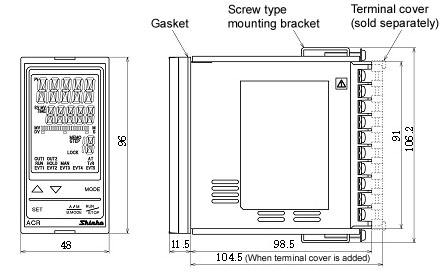
ACR-13A, ACR-15A: 48x96x110mm (WxHxD) |
| Mounting |
Flush |
| Display |
ACD-13A
ACD-15A |
PV display: 24.0x11.0mm (HxW)
SV/MV/TIME display: 14.0x7.0mm (HxW) |
ACR-13A
ACR-15A |
PV display: 14.0x5.4mm(HxW)
SV/MV/TIME display: 10.0x4.6mm (HxW) |
|
|
|
| Indication performance |
|
| Control performance |
|
| Standard functions |
| Event output |
2 points of Event output
Selectable during Event output allocation by keypad
-Alarm output; High limit
-Alarm output; Low limit
-Alarm output; High/Low limits
-Alarm output; High/Low limits independent
-Alarm output; High/Low limit range
-Alarm output; High/Low limit range independent
-Alarm output; Process high
-Alarm output; Process low
-Alarm output; High limit with standby
-Alarm output; Low limit with standby
-Alarm output; High/Low limits with standby
-Alarm output; High/Low limits with standby independent
-Timer output
-Timer output (Control ON while timer ouput is ON)
-Heater burnout alarm output (When W option is added)
-Loop break alarm output
-Time signal output
-Output during AT
-Pattern end output |
| Console communication |
By connecting the USB communication cable (CMB-001)
to the Console connector of the instrument, the following
operations can be conducted from the external computer
using the Console software SWS-AC001M.
Console communication and Serial communication cannot
be used together.
-Reading and setting of the SV, PID values and various
set values
-Reading of the PV and action status
-Function change
Communication specifications
-Communication protocol: Shinko protocol
-Communication interface: C-MOS level
-Communication method: Half-duplex communication
-Synchronization method: Start-stop synchronization
-Communication speed: 9600bps
-Data bit: 7
-Parity: Even
-Stop bit: 1
-Exclusive cable |
| Attached functions |
Sensor correction, Set value lock, Auto/Manual
switching, Program control, Set value ramp, Power failure
countermeasure, Self-diagnosis, Automatic cold junction
temperature compensation, Burnout, Input abnormality,
Warm-up indication, PV color switching, Timer, Bar graph
indication |
|
|
| Optional functions |
Event input
(EI option) |
If this option and Serial communication (C, C5 option)
are added together, Event input EVI3 and EVI4 cannot
be used.
4 points of event input
Selectable during Event input allocation by keypad
-Set value memory function
-Control ON/OFF
-Direct/Reverse control action
-Timer function Start/Stop
-PV display; PV holding
-PV display; PV peak value holding
-Preset output
-Auto/Manual control
-Remote/Local
-Program mode; RUN/STOP
-Program mode; Holding/Not holding
-Program mode; Advance function
-Integral action holding |
Event output
(EVT3 option) |
(Only for ACD-13A, ACR-13A)
If this option is added, Heating/Cooling control (DR,
DS, DA option) or Insulated power output (P24 option)
cannot be added together.
EVT1 to EVT3 will be added using a common terminal.
Selectable by keypad during Event output allocation
(the same as the standard Event output function) |
Event output
(EVT5 option) |
EVT4, EVT5 can be added.
Selectable by keypad during Event output allocation
(the same as the standard Event output function) |
Heater burnout alarm
(W option) |
(Only for ACD-13A, ACR-13A)
Monitors heater current with CT (current transformer),
and detects burnout.
Rated current: Single-phase; 20A, 100A, 3-phase; 20A,
100A
Setting range: 0.0 to 20.0A or 0.0 to 100.0A
Setting accuracy: Within  5%
of the rated current 5%
of the rated current
Action point: set value |
Heating/Cooling control output
(Dx option) |
(Only for ACD-13A, ACR-13A)
If this option is added, Event output (EVT3 option)
or Insulated power output (P24 option) cannot be added
together.
If this option is added, Event output EVT2 cannot be
used.
An action mode is selectable by front keypad.
-Air cooling: Linear characteristic
-Oil cooling: 1.5th power of the linear characteristic
-Water cooling: 2nd power of the linear characteristic
OUT2 output
-DR: Relay contact 1a1b
-DS: Non-contact voltage (for SSR drive)
-DA: DC current |
Serial communication
( C, C5 option)
|
If this option and Event input
(EI option) are added together, Event input EVI3 and EVI4
cannot be used.
The following operations can be carried out from the external
computer.
-Reading and setting of the SV, PID values and various
set values
-Reading of the PV and action status
-Function change
Communication specifications
-Communication line: C(EIA RS-232C), C5(EIA RS-485)
-Communication method: Half-duplex communication
-Synchronization method: Start-stop synchronization
-Communication speed: 9600, 19200, 38400bps (Selectable
by keypad)
-Data bit: 7, 8
-Parity: Even, Odd, No parity
-Stop bit: 1or 2 (Selectable by keypad)
-Communication protocol: Shinko protocol, Modbus ASCII,
Modbus RTU (Selectable by keypad)
Digital external setting via Shinko programmable controllers:
Receives the digital set values from the Shinko programmable
controllers (PC-900, PCD-33A with SVTC option). |
External setting input
(Ex option) |
SV adds external analog signal to remote bias value.
Setting signal
-EA(4-20): DC current 4-20mA DC
-EA(0-20): DC current 0-20mA DC
-EV(1-5): DC voltage 1-5V DC
-EV(0-1): DC voltage 0-1V DC
Input sampling 0.25sec |
Transmission output
(Tx option)
|
Converting the value (PV, SV,
MV or DV transmission) to analog signal every 0.125 seconds,
outputs the value in current or voltage.
Resolution: 1/12000
Output
-TA: DC current 4 to 20mA DC (load resistance Max. 500)
-TV: DC voltage 0 to 1V DC (load resistance Min.100k)
Output accuracy: Within 0.3%
of the transmission output span |
Insulated power output
(P24 option) |
(Only for ACD-13A, ACR-13A)
If this option is added, Event output (EVT3 option) or
Heating/Cooling control (DR, DS, DA option) cannot be
added together.
If this option is added, Event output EVT2 cannot be used.
Output voltage: 243V
DC (when load current is 30mA DC)
Ripple voltage: Within 200mV DC (when load current is
30mA DC)
Max load current: 30mA DC |
|
|
| Insulation, Dielectric strength |
Insulation resistance |
10M or more, at 500V DC
When OUT1 and OUT2 are non-contact voltage or DC current
output, OUT1 is
not insulated from OUT2. |
| Dielectric strength |
Between Power terminal - Ground: 1.5kV AC
for 1minute
Between Input terminal - Ground: 1.5kV AC for 1minute
Between Input terminal - Power terminal: 1.5kV AC for
1minute |
|
|
| Other |
| Ambient temperature |
0 to 50 |
| Ambient humidity |
35 to 85%RH (Non-condensing) |
Drip-proof/
Dust-proof |
IP66 for the front panel |
|
|
|
|
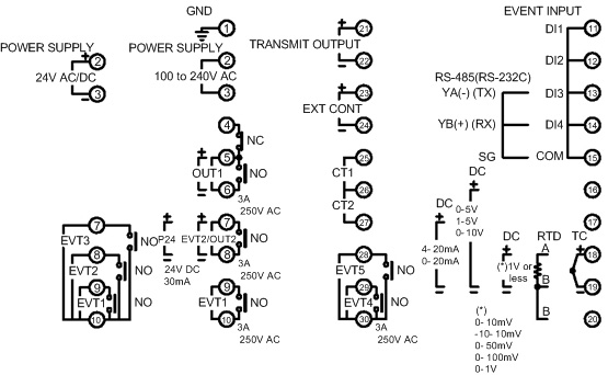
| |
ACD-13A
 |
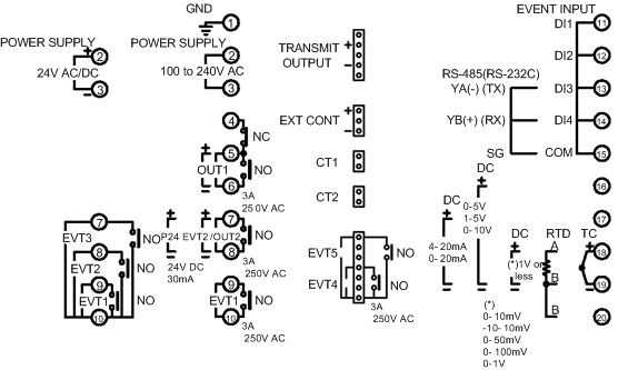
ACR-13A
 |
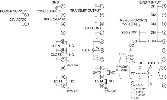
ACD-15A_Terminal_arrangement
 |
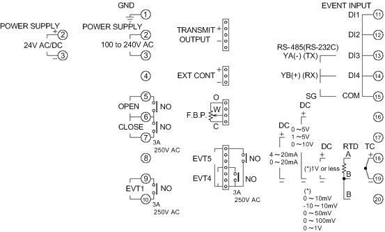
ACR-15A_Terminal_arrangement
 |
|
|
| |
External dimensions (Scale: mm) |
| |
ACD-13A, ACD-15A
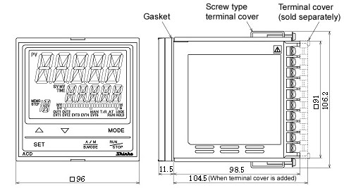
ACR-13A, ACR-15A
 |
| |
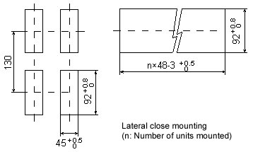
Panel cutout (Scale: mm) |
|
ACD-13A, ACD-15A
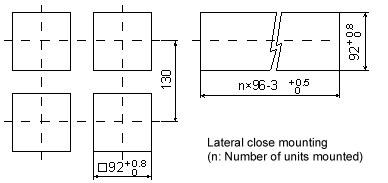
ACR-13A, ACR-15A
 |
|