|
|
|
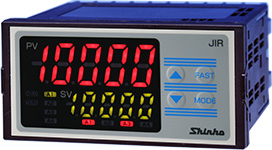
Digital Indicator |
|
| JIR-301-M |
|
Thermocouple (10 types), RTD (2 types)
Direct current (2 types) and DC voltage (4 types) |
|
| Standard Transmission output, 3-point alarm output |
Converting the input value to analog signal every 125 ms, outputs the value in direct current 4 to 20mA DC.
3-point alarm output function is also equipped as a standard function. |
|
| IP66 structure (for the front panel) allows usage in harsh environments, such as exposure to water or dust. |
|
| The following optional functions can be used: Serial communication [Shinko protocol, Modbus protocol (ASCII mode, RTU mode)], Alarm 4 output, 2-points of Transmission output, Power for 2-wire transmitter. |
|
 |
 |
| Input |
| Thermocouple |
K, J, R, S, B, E, T, N, PL-II, C(W/Re5-26)
External resistance: 100  max. (for B input, 40 max.) max. (for B input, 40 max.) |
| RTD |
Pt100, JPt100 3-wire type (Allowable input lead wire resistance: 10 max. per wire) |
| Direct current |
0 to 20 mA DC, 4 to 20 mA DC
Input impedance: 50 max.
Allowable input current: 50 mA DC max. |
| DC voltage |
0 to 1 V DC
Input impedance: 1 M min.
Allowable input voltage: 5 V DC max.
Allowable signal source resistance: 2 k max. |
0 to 5 V DC, 1 to 5 V DC, 0 to 10
V DC
Input impedance: 100 k min.
Allowable input voltage: 15 V DC max.
Allowable signal source resistance: 100 max. |
|
| Accuracy |
| Thermocouple |
Within  0.2%
of each input span 1
digit, or within 2 0.2%
of each input span 1
digit, or within 2  (4 (4  ), whichever is greater ), whichever is greater
However R, S inputs, 0 to 200 (32 to 392 ):
Within 6 (12 )
B input, 0 to 300 (32 to 572 ):
Accuracy is not guaranteed.
K, J, E, T, N inputs, Less than 0 (32 ):
Within 0.4%
of input span 1
digit |
| RTD |
Within 0.1%
of each input span1
digit, or within 1 (2 ), whichever is greater |
Direct current,
DC voltage
|
Within 0.2%
of each input span1
digit |
|
| Input sampling peirod |
125 ms |
| Event input function |
Selects Event input function from 3 types of HOLD function and 2 types of Alarm HOLD function. Not available if Serial communication (C5 option) is ordered. |
A1 output,
A2 output,
A3 output |
The alarm action point can be set at random (process alarm), and if the input reaches the randomly set action point, the alarm output turns ON or OFF corresponding to the alarm type and Energized/De-energized selection. The alarm type can be selected from; No alarm action, High limit alarm, Low limit alarm, High limit with standby alarm, Low limit with standby alarm and High/Low limit range alarm (for A3 output only). High/Low limit range alarm can be selected when A1 High limit alarm (High limit with standby alarm) and A2 Low limit alarm (Low limit with standby alarm) are combined, or when A1 Low limit alarm (Low limit with standby alarm) and A2 High limit alarm (High limit with standby alarm) are combined.
| Action |
ON/OFF action |
| Hysteresis |
0.1 to 100.0 ()
Direct current, DC voltage input: 1 to 1000 (The placement of the decimal point follows the selection.) |
| Alarm HOLD function |
Enables/Disables the Alarm HOLD function.
If Alarm HOLD function is set to “Enabled”, and if the alarm is ON, the alarm output ON status will be maintained until the following is conducted.
• The FAST key is pressed for approx. 3 seconds.
• The power is turned OFF.
• The HOLD is cancelled by the Event input function.
During Alarm HOLD, corresponding alarm action indicator flashes. |
Output
|
Relay contact 1a
Control capacity: 3 A 250 V AC (resistive load)
Electrical life: 100,000 cycles |
|
| Transmission output 1 |
Converting the PV to analog signal every 125 ms, outputs the value in direct current. (Unaffected by the HOLD function) (When using the Transmission output 1 value as an input for other instruments, check that the input impedance of these instruments is smaller than the maximum load resistance of Transmission output 1.)
| Resolution |
12000 |
| Direct current |
4 to 20 mA DC (Load resistance: Max. 550 ) |
| Output accuracy |
Within 0.3% of transmission output span |
Response time
|
400 ms+ Input sampling period (0%→90%) |
|
| Power supply voltage |
| Model |
JIR-301-M |
JIR-301-M 1 |
| Power supply voltage |
100 to 240 V AC 50/60Hz |
24 V AC/DC 50/60Hz |
Allowable voltage fluctuation range
|
85 to 264 V AC |
20 to 28 V AC/DC |
|
| Power consumption |
| Supply Voltage |
Power Consumption |
| 100 to 240 V AC |
Approx. 8 VA (When maximum options are ordered: Approx.10 VA) |
| 24 V AC |
Approx. 6 VA (When maximum options are ordered: Approx.9 VA) |
24 V DC
|
Approx. 4 W (When maximum options are ordered: Approx.7 W) |
|
| Options |
Serial communication(RS-485),
Alarm output 4(A4),
Insulated power output,
Power for 2-wire transmitter,
Transmission output 2,
User specified transmission output,
Terminal cover, etc. |
|
|
|
|