|
|
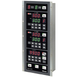
| 2ch Oven Controller |
|
| BOC-600 |
|
| For Making Bread and Confectioneries |
| Developed for ovens making bread and confectioneries, with 2-channel control (Top/Bottom Heater temperature control). |
|
| Programming Function Provided |
15 menus (8-steps/menu) can be set.
[If the M30 option is ordered, a maximum of 30 menus can be used.] |
|
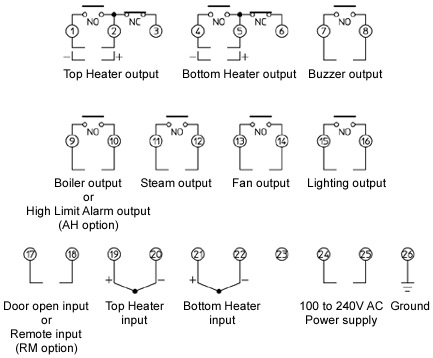
| Various Output Terminals Equipped as Standard
|
| Lighting output, Buzzer output, Boiler output, Steam output, Fan output are standard features.
|
|
| Remote Input Function (Optional) |
| The oven can be preheated (automatically) without pressing the POWER key, by connecting to a calendar timer. |
|
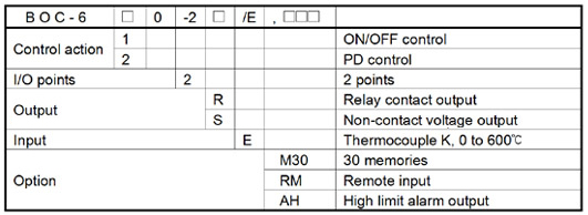
| Model |
 |
 |
 |
| Rating |
| Rated Scale |
0 to 600
|
| Input |
Thermocouple K
External resistance: 100 or less or less
|
| Supply Voltage |
100 to 240V AC 50/60Hz |
| Allowable Voltage Fluctuation Range |
85 to 264V AC |
|
|
|
| General structure |
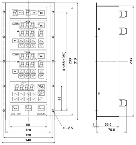
| External Dimensions |
140x310x88mm(WxHxD)
|
| Mounting |
Flush
|
| Front Panel |
Membrane sheet
|
| Indicating Structure |
Display
| Menu Display |
Red LED 1 digit,
character size 14.3x8mm (HxW) |
| Step Display |
Green LED 1 digit,
character size 14.3x8mm (HxW) |
Top Heater
temperature Display |
Red LED 3 digit,
character size 14.3x8mm (HxW) |
| Top Heater SV Display |
Green LED 3 digit,
character size 14.3x8mm (HxW) |
Top Heater
Output Limit Display |
Red LED 1 digit,
character size 14.3x8mm (HxW) |
Bottom Heater
temperature Display |
Red LED 3 digit,
character size 14.3x8mm (HxW) |
Bottom Heater
SV Display |
Green LED 3 digit,
character size 14.3x8mm (HxW) |
Bottom Heater
Output Limit Display |
Red LED 1 digit,
character size 14.3x8mm (HxW) |
| Timer Display |
Red LED 4 digit,
character size 14.3x8mm (HxW) |
|
| Setting Structure |
Setting method: Input by the membrane sheet key.
|
|
|
|
| Indication performance |
|
| Control performance |
| Setting Accuracy |
The same as indication accuracy |
| Control Action |
PD control
ON/OFF control action: When proportional band is set to 0.0.
Individual settings for Top and Bottom Heater
| Proportional band |
0.0 to 99.9
(ON/OFF control when set to 0.0) |
| Derivative time |
0 to 300 sec |
| Manual reset |
-19.9 to 99.9 |
Common settings to Top and Bottom Heater
| Proportional cycle |
1 to 120 sec |
| ON/OFF hysteresis |
0.1 to 10.0 |
|
| Control Output |
| Relay contact output 1a 1b |
Control capacity: 3A 250V AC (resistive load)
1A 250V AC (inductive load cos =0.4) =0.4)
Electrical life: 100,000 cycles |
Non-contact voltage
output (for SSR
drive) |
12V DC 15% Max 40mA (short circuit protected) 15% Max 40mA (short circuit protected) |
|
| Buzzer output |
Relay contact output 1a, Control capacity: 3A 250V AC (resistive load)
1A 250V AC (inductive load cos=0.4) |
| Boiler Output |
Relay contact output 1a, Control capacity: 3A 250V AC (resistive load)
1A 250V AC (inductive load cos=0.4) |
| Steam Output |
Relay contact output 1a, Control capacity: 3A 250V AC (resistive load)
1A 250V AC (inductive load cos=0.4) |
| Fan Output |
Relay contact output 1a, Control capacity: 3A 250V AC (resistive load)
1A 250V AC (inductive load cos=0.4) |
| Lighting Output |
Relay contact output 1a, Control capacity: 3A 250V AC (resistive load)
1A 250V AC (inductive load cos=0.4) |
|
|
|
| Standard functions |
| Memory Function |
If the Memory Function is selected from the Control Type selection, 15
memories can be set.
If 30 Memories (M30 option) is added, 30 memories can be set.
One memory can include Top and Bottom Heater temperatures, Timer set value, Output Limits (Top and Bottom Heater outputs), high limit alarm value (AH option) and Steam Time.
|
| Program Function |
If the Program Function is selected from the Control Type selection, 15
menus (8-steps/menu) can be set.
If 30 Memories (M30 option) is added, 30 menus can be set.
In Automatic Operation, 8 steps are automatically performed.
If either Top or Bottom Heater temperature is 0, and if Timer is set to a value other than 0, operation will commence.
However, if Top and Bottom Heater temperatures of all remaining steps are 0, the unit will not proceed to the next step, but control is performed with the Top and Bottom Heater temperatures of the last step.
If Timer value is set to 0, the step will be skipped, and will proceed to the next step.
In Manual Operation, steps are performed one by one. Even if Timer time has elapsed, the unit will not proceed to the next step.
One step can store Step Temperatures (Top and Bottom Heater
temperatures), Timer set value, Output Limits (Top and Bottom Heater Output Limits), High Limit Alarm value (AH option) and Steam Time.
|
| Output Limit Function |
Sets Output High Limit value.
Output Limit can be changed without entering the Top or Bottom Heater
Setting mode.
If 2 seconds elapse without any operation after the set value has been
changed, the value at the given time will be registered.
|
| Buzzer Output |
For the Memory Function, when the preset Timer counting is completed,
the Buzzer output is turned ON.
For the Program Function with automatic operation, when the last step is finished, the Buzzer output is turned ON.
For the Program Function with manual operation, when the step time is
finished, the Buzzer output is turned ON.
To turn the Buzzer output OFF, press the BUZZER RESET Key or open the door.
|
| Boiler Output |
Every time the BOILER Key is pressed, the Boiler output is turned ON or
OFF.
If High Limit Alarm output (AH option) is added, the Boiler output is disabled.
|
| Steam Output |
If the STEAM Key is pressed, the Steam output is turned ON for the time
set in the Steam Time setting.
If the STEAM Key is pressed again, the Steam output will be turned OFF.
|
| Fan Output |
The Fan output is turned ON in the PV/SV Display mode.
|
| Lighting Output |
Every time the LIGHT Key is pressed, the Lighting output is turned ON or
OFF.
|
| Door Open Input |
If the door is opened while Timer is working, the Timer can be suspended
temporarily.
Even though the door is closed, the Timer does not start again.
By pressing the START/STOP Key, the Timer can be released, and Timer
action will continue.
If the door is opened while Buzzer output is ON, the Buzzer output will be
turned OFF.
If the Remote Input (RM option) is added, the Door Open Input will be
disabled.
|
|
|
|
| Optional functions |
30 Memories
(Option code: M30) |
If the Memory Function is selected from the Control Type selection, 30
memories can be set.
One memory can include Top Heater and Bottom Heater temperatures,
Timer set value, Output Limits (Top Heater and Bottom Heater Output
Limits), High Limit Alarm value (AH option) and Steam Time.
If Program Function is selected from the Control Type selection, 30 menus (8-steps per menu) can be set.
One step can include step temperatures (Top Heater and Bottom Heater
Temperatures), Timer set value, Output Limits (Top Heater and Bottom
Heater Output Limits), High Limit Alarm value (AH option) and Steam Time.
|
Remote Input
(Option code: RM) |
Remote input function starts/stops control via external contact signal.
Remote input terminals Closed: Control starts (Starts with Top and Bottom heater temperature control outputs ON and Lighting output ON.)
Remote input terminals Open: Control stops. While Remote input terminals are open, control can start/stop via front keypad operation. |
High Limit Alarm
Output
(Option code: AH) |
Deviation setting from the set temperature, and if the temperature exceeds the range during operation, the alarm output will be turned ON.
Common to Top Heater and Bottom Heater setting items.
|
|
|
|
| Other |
| Power Consumption |
Approx. 14VA |
| Ambient Temperature |
0 to 50 |
| Ambient Humidity |
35 to 85%RH (Non-condensing) |
| Weight |
Approx. 1500g |
|
|
|
|
|
| |
|
If High Limit Alarm output (AH option) is added, the Boiler output is disabled.
If Remote Input (RM option) is added, the Door Open Input is not effective. |
|
|
| |
External dimensions (Scale: mm) |
| |
 |
| |
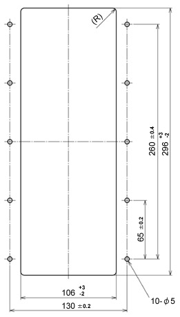
Panel cutout (Scale: mm) |
|
|
|