|
|
| Programmable Controller |
|
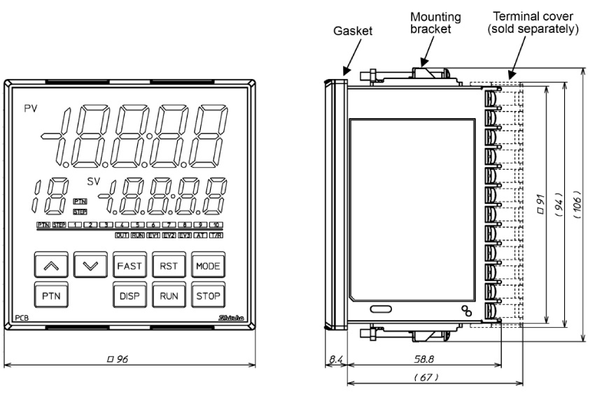
| PCB1 |
|
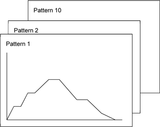
| Program capacity: 10-patterns, 10-steps/pattern
|
| Program capacity with 10-patterns, 10-steps/pattern
Using pattern link function, up to 100 steps of program control can be carried out. |
|
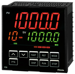
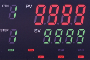
| Easier viewing large display
|
The large PV Display is useful for indicating a wide range of measurement ranges.
Character size: 24 x 11 mm (H x W) |
PCB1
PCD-33A
|
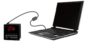
| Power supply and quick setup using the Tool cable and USB cable
|
Initial settings can be easily performed from a PC using the Tool cable and USB cable.
If the Tool cable (CMD-001, sold separately) is used, the power can be supplied to the PCB1 (from USB terminal of a PC). |
|
| Drip-proof / Dust-proof (IP66)
|
| IP66 (only for the front panel) allows usage in harsh environments where the controller is exposed to water or dust.
|
|
 |
 |
| |
 |
|
|
| Input |
| Input |
| Thermocouple |
K, J, R, S, B, E, T, N, PL-II, C(W/Re5-26)
External resistance: 100  max. However, B: 40 max. max. However, B: 40 max. |
| RTD |
Pt100, JPt100 3-wire type
Allowable input lead wire resistance: 10 max. per wire |
| Direct current |
0 to 20 mA DC, 4 to 20 mA DC
Input impedance: 50
Allowable input current: 50 mA max. |
| DC voltage |
0 to 1 V DC
Input impedance: 1 M min.
Allowable input voltage: 5 V DC max.
Allowable signal source resistance: 2 k max. |
0 to 5 V, 1 to 5 V, 0 to 10 V DC
Input impedance: 100 k min.
Allowable input voltage: 15 V DC max.
Allowable signal source resistance: 100 max. |
|
Event input
(Optional) |
| Input points |
2 points |
| Circuit current when closed |
Approx. 16 mA |
| Action |
Edge action
When the power is turned on, level action is engaged. |
|
|
|
| Output |
| Control output |
Relay contact
1a |
Control capacity: 3 A 250 V AC (resistive load)
1 A 250 V AC (inductive load cos =0.4) =0.4)
Electrical life: 100,000 cycles
Minimum applicable load: 10 mA 5 V DC |
Non-contact voltage
(for SSR drive) |
12 V DC 15% 15%
Max. 40 mA (Short circuit protected) |
| Direct current |
4 to 20 mA DC
Resolution: 12000
Load resistance: Max. 550 |
|
Event output
EV1 to EV3 |
Relay contact
1a |
Control capacity: 3 A 250 V AC (resistive load)
1 A 250 V AC (inductive load cos=0.4)
Electrical life: 100,000 cycles
Minimum applicable load: 10 mA 5 V DC |
|
Control output OUT2
(Optional) |
|
Relay contact
1a |
Control capacity: 3 A 250 V AC (resistive load)
1 A 250 V AC (inductive load cos=0.4)
Electrical life: 100,000 cycles
Minimum applicable load: 10 mA 5 V DC |
Non-contact voltage
(for SSR drive) |
12 V DC15%
Max. 40 mA (Short circuit protected) |
| Direct current |
4 to 20 mA DC
Resolution: 12000
Load resistance: Max. 550 |
|
Transmission output
(Optional) |
| Resolution |
12000 |
| Output |
4 to 20 mA DC (Load resistance: Max. 550 ) |
| Output accuracy |
Within 0.3% of Transmission output span |
| Response time |
400 ms + Input sampling period (0%-->90%) |
|
Insulated power output
(Optional) |
| Output voltage |
243 V DC (When load current is 30 mA DC) |
| Ripple voltage |
Within 200 mV DC (When load current is 30 mA DC) |
| Max. load current |
30 mA DC |
|
|
|
| Performance |
| Base accuracy |
At ambient temperature 23 (for a single unit mounting) (for a single unit mounting)
|
Effect of ambient
temperature
|
Within 50 ppm/ of each input span |
| Input sampling period |
125 ms |
| Time setting accuracy |
Within 0.5% of setting time |
|
|
| Program Performance |
| Number of patterns |
10 (Linkable) |
| Number of steps |
100 (10-steps/pattern) |
| Number of repetitions |
0 to 10000 times (Repetitions disabled when set to 0.) |
| Program time range |
0 to 99 hours 59 minutes/step or 0 to 99 minutes 59 seconds/step
(When ---- is set, Fixed value control is performed using the step SV.) |
| Wait value |
Thermocouple, RTD input without decimal point: 0 to 20% of input span
DC voltage, current input: 0 to 20% of scaling span (The placement of the decimal point follows the selection.)
(The Wait function is disabled when set to 0 or 0.0.) |
|
|
|
|
|